
Total runout
Circular runout everywhere at once — which is a much larger promise than it first sounds.
What it controls
Total runout limits how much an entire surface rises and falls against an indicator while the part turns about a datum axis. Unlike circular runout it is judged over the whole surface together rather than section by section.
That makes it the broadest control in the standard for a rotating feature. Roundness, straightness, taper and eccentricity all fall inside a single number, because every one of them moves the indicator during the sweep.
The tolerance zone
On a cylindrical surface, two coaxial cylinders a set radial distance apart, coaxial with the datum axis. On a face perpendicular to the axis, two parallel planes that distance apart, square to the datum axis. The whole surface has to lie between them.
Try it in 3D
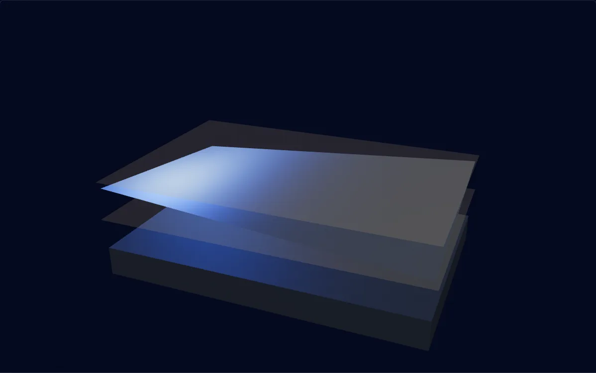
Within tolerance
Drag to exaggerate the deviation. The part is shown far out of scale so the zone stays visible.
Reading the callout
The whole of this surface has to stay within 0.05 mm total indicator movement as the part turns about datum A and the indicator traverses its length.
When to reach for it
- A journal that a seal or bearing rides along, where the fit has to be the same at every point of its length.
- A rotor or a pulley face where the whole surface has to run true, not just one line on it.
- A part where taper along the length would cause trouble and circular runout would let it through.
How it is measured
- The part turns on its datum feature while the indicator traverses along the surface. The reading is the full range — the highest point minus the lowest across the entire surface, with the indicator never re-zeroed during the sweep. Re-zeroing at each section turns it back into a circular runout check and hides exactly the taper total runout exists to catch.
- On a CMM the surface is scanned in several sections and the software fits the smallest pair of coaxial cylinders containing all the points.
- The indicator path has to cover the full toleranced length, since a sweep that stops short simply has not tested the rest.
Getting it right
- Set the value with the length in mind, since total runout accumulates every error along the surface and a long journal is a much harder job than a short one at the same number.
- Use circular runout where each section standing alone is the real requirement, as it is quicker to check and easier to hold.
- Name the same datum the part runs on in service, because as with circular runout the whole statement is relative to that axis.
Common questions
What is the difference from circular runout?
Circular runout judges each cross-section on its own, so a shaft can pass every section and still be tapered or barrelled along its length. Total runout judges the whole surface at once, so taper, barrelling and bending all count against the same number. At the same value total runout is always the harder requirement, sometimes by a wide margin.
What errors does total runout catch?
On a cylindrical surface: roundness error, straightness of the axis, taper, barrelling and eccentricity from the datum axis, all at once. On a face perpendicular to the axis it catches flatness error and perpendicularity together. It is the most inclusive single control the standard offers for a rotating feature, which is both its strength and the reason to think before writing a tight value.
Total runout or cylindricity?
Cylindricity asks whether the surface is a good cylinder in its own right and needs no datum. Total runout asks whether it runs true about a specific axis, and needs one. If the part rotates in service, total runout usually describes the real requirement better and is far quicker to check with an indicator. If the surface has to be a good cylinder regardless of what it turns about, cylindricity is the honest control.
Why is total runout harder to hold?
Because errors accumulate along the surface rather than being forgiven section by section. A shaft ground between centres will have some taper, some deflection under the wheel, and some eccentricity from its centres, and total runout adds all of it into one reading. Where the value is tight, the practical answers are grinding between the same centres used for measurement, and taking the last passes with little enough force that the part stops pushing away.
These pages explain the published standards for reference and describe the tolerance zones they define. The values shown in the examples are illustrative. What a given part can hold depends on its geometry, material and process, and is agreed per drawing.