
Four processes. One point of contact.
CNC machining, stamping, injection moulds, sheet metal — the same drawing discipline and the same documentation, whichever process makes the part. Tolerances down to 1 µm on the critical features defined in the drawing.
Four process families
Every dimension on the sheet becomes a dimension on the part.
Scroll, and watch a drawing turn into steel. The tolerances hold all the way through — they're what the four processes below are built for.
And which general tolerance governs the rest?Illustrative part, our own drawing
Keep scrolling
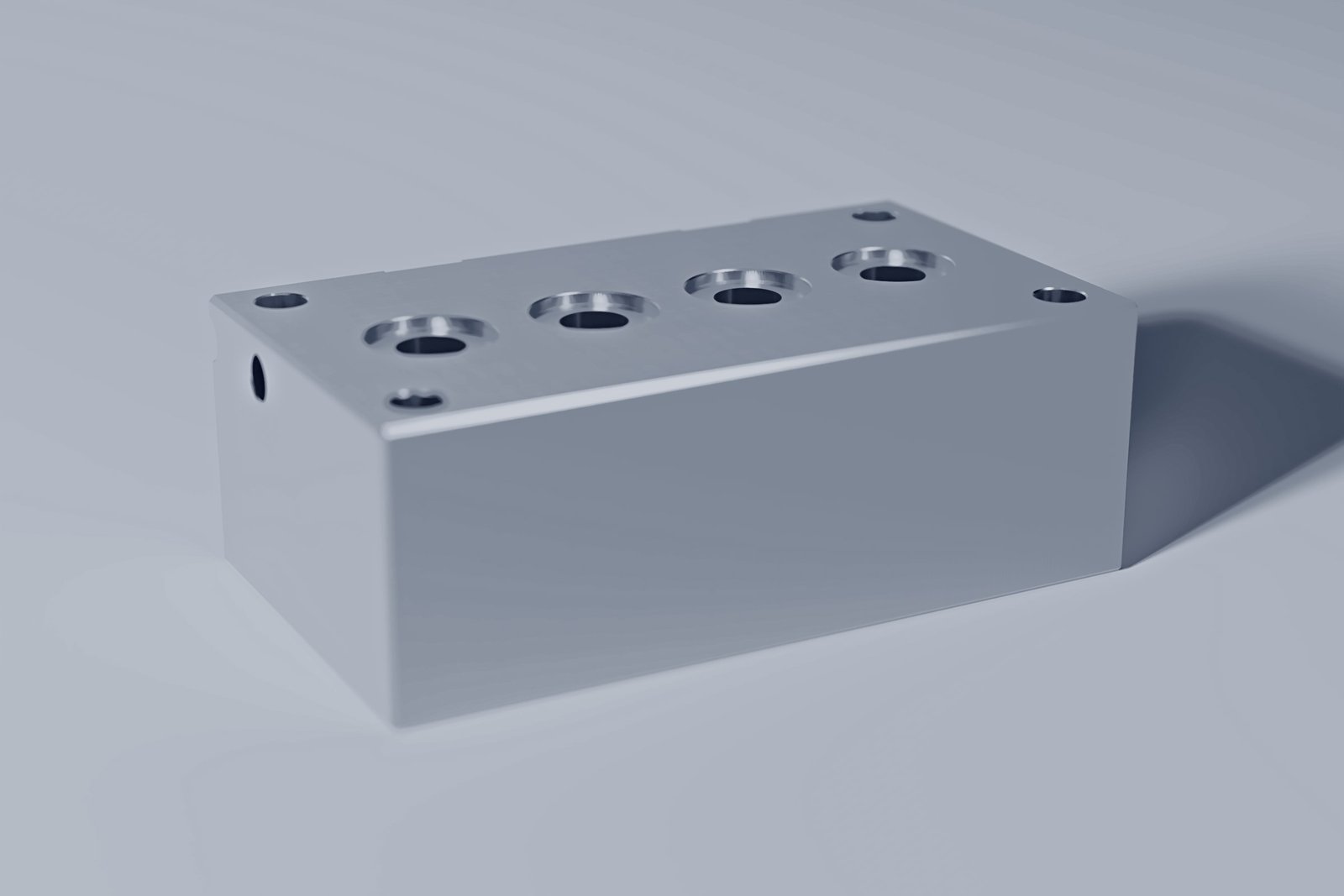
CNC machining: milling, turning and EDM, from prototype to series
3-, 4- and 5-axis milling
Complex geometries in few set-ups; housings, covers, brackets.
Turning & Swiss-type
Small and micro parts with a high length-to-diameter ratio, in series.
Wire & sinker EDM
Wire and die-sink EDM for hardened materials and internal profiles that lie beyond the reach of milling, plus surface, cylindrical and profile grinding.
Prototype → series
The same technical documentation from the first part to series production.
Common materials: aluminium, tool steels, stainless steel, brass, copper, engineering plastics. Tight tolerances, down to 1 µm on the critical features defined in the drawing.
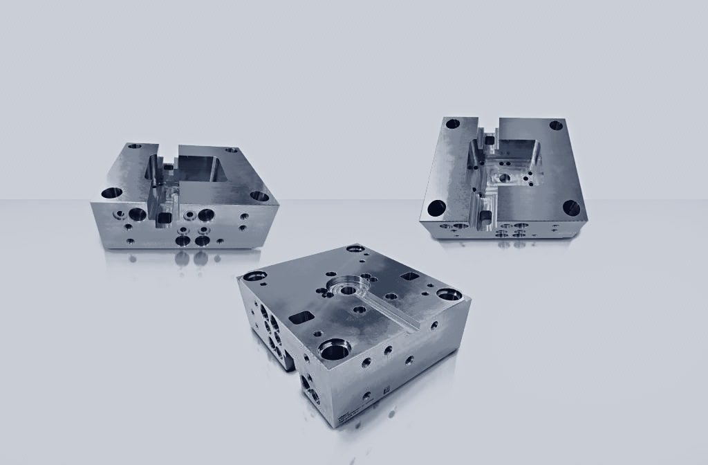
Injection moulds: the complete mould, and every component in it
Design to moulded part
Mould design → mould trials → moulded part production
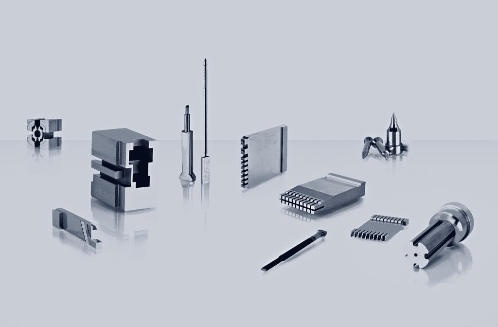
Every component of the mould
Plates and mould bases, cavities and cores, inserts, ejector pins and sleeves, cylindrical pins, guide elements, sliders, and cooling channels and inserts
Coatings for moving elements
DLC on ejectors and sliders, dry running
Rapid tooling
Validate geometry and material before the series mould
Flow simulation
Material flow simulation before committing to tooling
1200 × 900 × 500mm
maximum mould size
400 & 1500kN
mould trial presses
DLC · CrN · TiNPVD
tooling coatings
Stamping: simple and progressive dies, and their active components
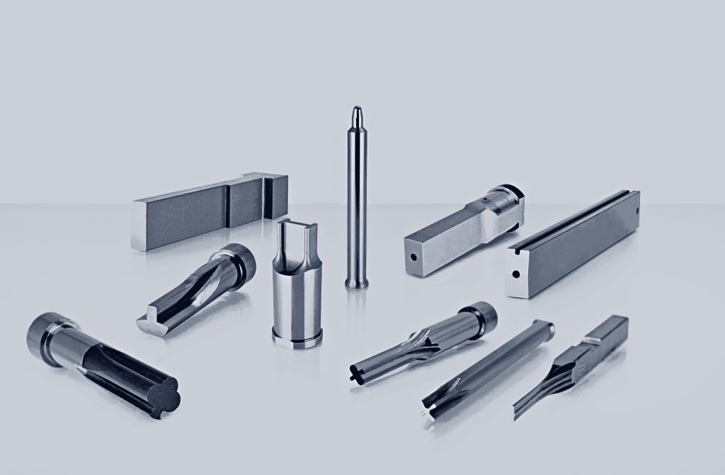
Punches
Stamping punches, profile punches and stepped punches
Cutting bushes & die plates
Cutting bushes, die plates, guides and locating elements
Simple & progressive dies
Single-stage and progressive dies, and bending modules for strip-fed parts
Profile grinding & EDM
Profile grinding and wire / die-sink EDM for complex contours
Carbide & PM steels
Carbide and powder-metallurgical steels for high volumes and difficult materials
Automotive applications
Terminals and contacts, blades, clips, stamped shields
For repeat orders we build a buffer stock, so the next call-off ships immediately.
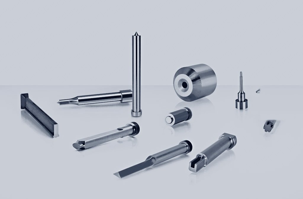
Sheet metal & forming: cutting, bending, deep drawing
01 / 04
Laser cutting & stamping
Laser cutting and sheet metal stamping, from coil or from blanks
02 / 04
Forming
Bending, deep drawing, sizing and straightening
03 / 04
Progressive tools
Progressive bending and drawing tools for series volumes
04 / 04
Finishing
Finishing and coating integrated into the same flow
Typical parts
EMI shields, brackets, clips and fasteners
Relevant for electronic assemblies: EMI shields and shielding cans, mounting brackets, clips and contact elements — in sheet metal, in series, with the coating applied in the same flow.
ISO 286 · fits & tolerances
H7/g6 isn't a label — it's how two parts behave together.
A tolerance callout on a drawing sets two independent zones: one for the hole, one for the shaft. Where those zones sit relative to each other decides whether the assembly slides, locates, or has to be pressed. Choose a fit and a nominal diameter below to see it happen.
The tolerance bands and the gap between hole and shaft are drawn enlarged so they read at all — the deviations themselves are the real ISO 286 values for the diameter selected above.
H7/g6 — Sliding clearance
The shaft is smaller than the hole at every size the tolerance allows, so the two parts always move freely and never bind.
- Hole (H7) · Upper deviation
- +21 µm
- Hole (H7) · Lower deviation
- 0 µm
- Shaft (g6) · Upper deviation
- -7 µm
- Shaft (g6) · Lower deviation
- -20 µm
Resulting fit
Clearance fit
min 7 µm – max 41 µm
Where a fit like this is used
A guide pillar running in its guide bush: thousands of open-and-close cycles, always sliding, never sticking.
Next step
Tell us which process your part needs.
Milling, stamping, injection moulds or sheet metal — send the drawing and we route it to the right process in the network.
Send a drawing