
Position
The most used symbol in the standard, and the one that replaces coordinate tolerancing with something that matches how parts actually assemble.
What it controls
Position limits how far a feature may sit from where the drawing says it belongs. The exact location is set by theoretically exact dimensions — TEDs in ISO, basic dimensions in ASME — measured from the datums, and the tolerance describes a zone around that exact point.
The feature keeps its size and its own shape and sits somewhere other than where the drawing puts it. The zone is fixed in orientation as well as in place, though, so a position tolerance also limits how far the axis may tilt. What is being located is usually a derived axis or median plane rather than a surface.
The tolerance zone
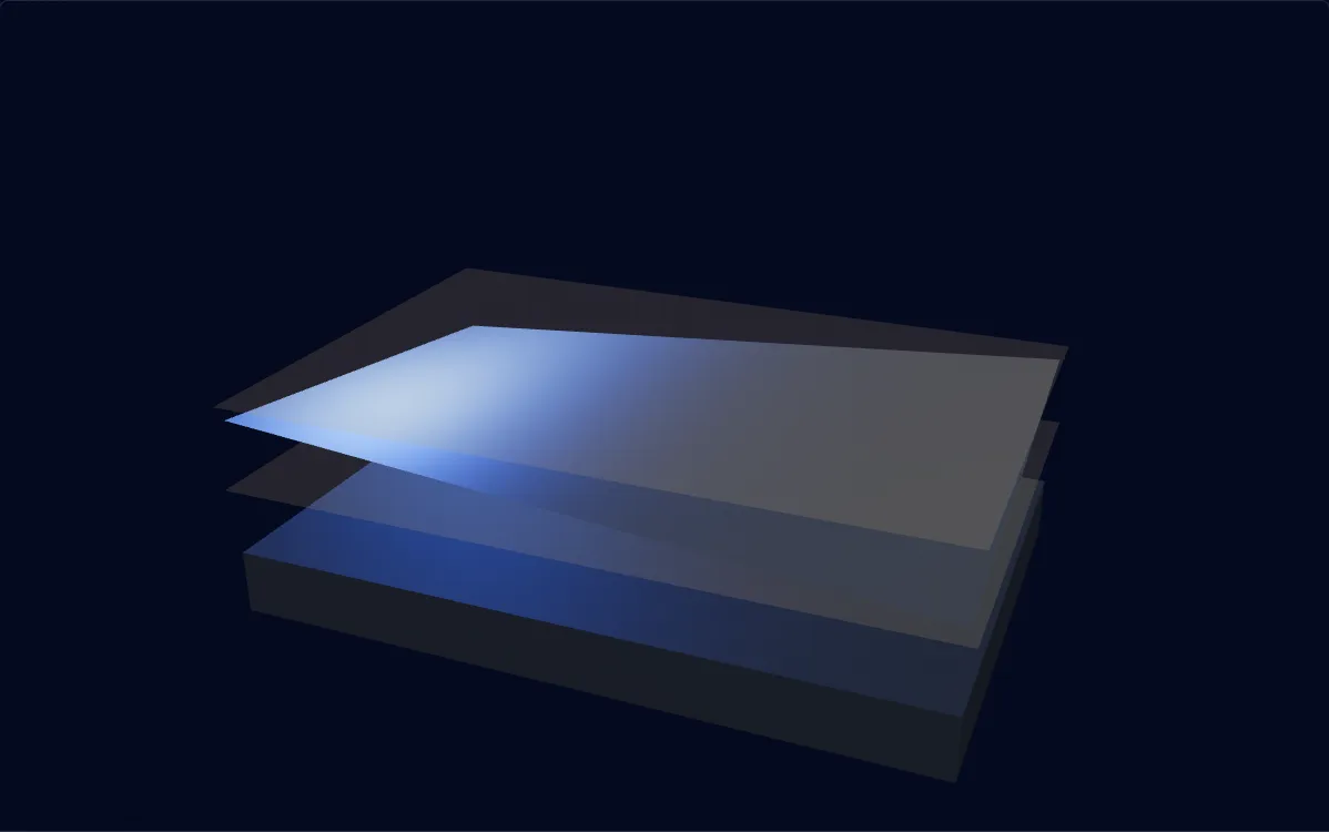
When the value carries a diameter symbol: a cylinder of that diameter, centred on the theoretically exact position and held at the orientation the theoretically exact dimensions define relative to the datums. The feature axis has to stay inside it in any direction. Without the diameter symbol the zone is two parallel planes of that width, which is the usual form on a slot or a width.
Try it in 3D
Within tolerance
Drag to exaggerate the deviation. The part is shown far out of scale so the zone stays visible.
Reading the callout
The axis of this hole has to lie inside a cylinder 0.1 mm across, centred on the position the theoretically exact dimensions give relative to A, B and C.
When to reach for it
- A pattern of clearance holes that has to line up with a mating part.
- A dowel or locating pin whose place decides where everything else ends up.
- Any feature previously toleranced with plus and minus coordinates, which position describes better and usually more generously.
How it is measured
- A CMM probes the datum features, builds the coordinate system, then measures the feature axis and reports its distance from true position.
- Check whether the software reports a radial deviation from true position or the diametral position value. Most packages report the diameter and have already applied the factor of two; where the output is a radius it has to be doubled before comparing it with a callout carrying the diameter symbol.
- A functional gauge checks a whole pattern in one operation where the callout carries a material condition modifier.
Getting it right
- Write the locating dimensions as theoretically exact, in boxes, so all the permitted variation lives in the tolerance zone.
- Add the material condition modifier where the requirement is genuinely assembly, since it widens the tolerance on most parts at no cost to function. It is valid only on a feature of size, it assumes size-then-position measurement or a gauge is acceptable, and some quality systems forbid it on safety-critical features — so it belongs on a clearance pattern rather than on a dowel hole that has to locate something.
- Remember what the diameter symbol does: with it, a callout of 0.1 mm allows the axis 0.05 mm from true position in any direction. Without it the 0.1 mm is the full width of a slab-shaped zone in the stated direction, which is a different requirement.
Common questions
Why is position better than plus-minus coordinates?
Because the zone shape matches the physics. Tolerancing a hole at ±0.05 mm in two directions gives a square zone, and a hole in the corner of that square is 0.071 mm from true position while one on the edge is only 0.05 mm — the same drawing accepts more error in one direction than another for no functional reason. A round zone treats every direction alike. Converting ±0.05 to the equivalent cylindrical zone of ⌀0.141 mm gives about 57 per cent more tolerance zone area, and every part in that extra area still assembles. How many more parts that actually recovers depends on how the process scatters — the gain is real, but it is a gain in permitted area rather than a fixed yield figure.
What are basic dimensions (theoretically exact dimensions) and why are they boxed?
ISO calls them theoretically exact dimensions, or TEDs; ASME calls them basic dimensions. Either way the dimension is exact and carries no tolerance of its own, and boxing it says so. The permitted variation is described entirely by the tolerance zone, so there is one statement of the requirement instead of two that would have to be reconciled.
Is the tolerance a radius or a diameter?
A diameter, whenever the value carries the diameter symbol, which is the usual case for round features. A callout of 0.1 mm therefore allows the axis to be 0.05 mm from true position. Reading it as a radius is a common and expensive mistake in both directions, since it either doubles the difficulty or accepts twice the error intended.
What does adding MMC to a position tolerance do?
It hands back tolerance as the feature departs from its maximum material size. A hole made larger than its smallest permitted size has room to spare, and the modifier makes that room available as extra position tolerance. On a clearance pattern this often doubles or triples what the drawing allows without affecting whether the parts go together.
These pages explain the published standards for reference and describe the tolerance zones they define. The values shown in the examples are illustrative. What a given part can hold depends on its geometry, material and process, and is agreed per drawing.