
Datums
Half of the geometric tolerances on a drawing mean nothing without these, and the letters are read in frame order rather than alphabetically.
What it controls
A datum is a theoretically exact reference — a plane, an axis or a point — that other tolerances are measured from. The real surface it is taken from is the datum feature, and the two are deliberately different things: the feature has form errors, the datum derived from it is perfect.
In practice the perfect datum is stood in for by something almost perfect: a surface plate, a chuck, a gauge pin. ASME Y14.5 calls that physical stand-in the datum feature simulator — the term most shops now use, and the one that replaced the older simulated datum. ISO 5459 comes at it from the other end, defining the datum through the feature associated with the real datum feature, the simulator being how that association is physically realised. Either way it is what the part actually touches during measurement.
The tolerance zone
A datum is a reference rather than a zone. Its job is to remove the part motion that would otherwise make a measurement depend on how the part happened to be sitting.
Try it in 3D
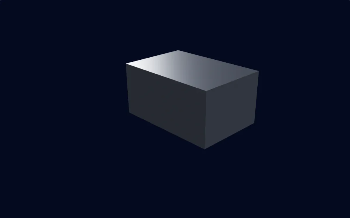
Degrees of freedom removed0 / 6
- Slide left / right
- Slide up / down
- Slide forward / back
- Rock forward / back
- Turn left / right
- Tilt side to side
Add the datums in order and watch the part lose its freedom to move. Three, then two, then one.
Reading the callout
The tolerance is measured with the part set against A first, then B, then C — in that order, which the frame states and the alphabet does not.
When to reach for it
- Any orientation, location or runout tolerance, all of which are measured against something and therefore need at least one datum.
- A part with a clear functional seating face, which is almost always the honest choice for the primary datum.
- An assembly where one feature locates everything else, which is the feature the datum reference frame should be built on.
How it is measured
- The part is set against physical simulators in frame order — the surface plate for the primary, an angle plate or stops for the secondary, a single stop for the tertiary.
- On a CMM the datum features are probed and the software fits the reference geometry, then reports every toleranced feature in that coordinate system.
- Repeatability is checked by taking the part off and setting it again; a datum scheme that gives a different answer on the second setup is telling you something useful.
Getting it right
- Choose the primary datum for how the part actually seats in service, since that is what makes the measured result predict the assembly.
- Read the letters in the order the frame lists them — A, B, C is the common case, but B, A, C means something different and is perfectly legal.
- Give a datum feature its own form tolerance where it matters, because everything measured from it inherits its errors.
Common questions
What is the difference between a datum and a datum feature?
The datum feature is the real surface on the part — it has waviness, roughness and form error like any other surface. The datum is the perfect geometric reference derived from it: a plane fitted to that surface, an axis fitted to that cylinder. Drawings label the feature; measurements use the derived reference.
Why does the order A, B, C matter?
Because each datum removes some of the part motion and the ones after it can only work with what is left. Setting a part on A first and then bringing it against B gives a different result from doing it the other way round. The order in the frame is the order in which the part is constrained, and it should normally mirror how the part is actually located in service — that is what makes the measured result predict the assembly.
What is the 3-2-1 rule?
A rigid part has six degrees of freedom: it can slide along three axes and rotate about three. Where the datums are three mutually perpendicular planes, a primary planar datum contacts at three points and removes three of them, a secondary contacts at two and removes two more, and a tertiary contacts at one and removes the last — three plus two plus one leaves the part in exactly one position, which is what makes a measurement repeatable. The counts change with the shape of the datum feature: a cylindrical primary datum removes four on its own, leaving translation along its axis and rotation about it. A secondary face fixes the axial position; whether a tertiary is needed after that depends on whether the part’s clocking about the axis matters.
Does every tolerance need three datums?
No, and adding unnecessary ones makes parts more expensive to inspect. Use as many as the requirement genuinely needs. Perpendicularity of a face to a base needs one. A hole located from a seating face and two edges needs three, even though the location itself is only in two directions — the face orients the part and the two edges fix it in the plane. Two are enough where a central bore does the locating and the part’s clocking about that bore has no function — the rotational freedom is then simply left open and the pattern judged as a unit, free to rotate. Form tolerances such as flatness and roundness need none at all.
These pages explain the published standards for reference and describe the tolerance zones they define. The values shown in the examples are illustrative. What a given part can hold depends on its geometry, material and process, and is agreed per drawing.