
Concentricity
A control that is precise about the right thing and awkward about everything else — which is why it appears far less often than it seems it should.
What it controls
ISO 1101 uses one symbol for two related controls. Applied to a cross-section it is concentricity: the centre of that section has to lie within a circular zone concentric with a datum point. Applied along a feature it is coaxiality, which is the case on a shaft or a bore: the derived median line has to lie within a cylindrical zone coaxial with the datum axis. Either way it is a location control, so the feature keeps its shape and simply sits off-centre.
The important word is derived. What is judged is never the surface itself but a feature taken from it — the centre of the section for concentricity, the median line running through those centres for coaxiality — which is precisely what makes it demanding to measure and what separates it from runout.
The tolerance zone
For coaxiality, a cylinder of the stated diameter coaxial with the datum axis, containing the derived median line. For concentricity in a single section, a circle of that diameter concentric with the datum point, containing the centre of that section.
Try it in 3D
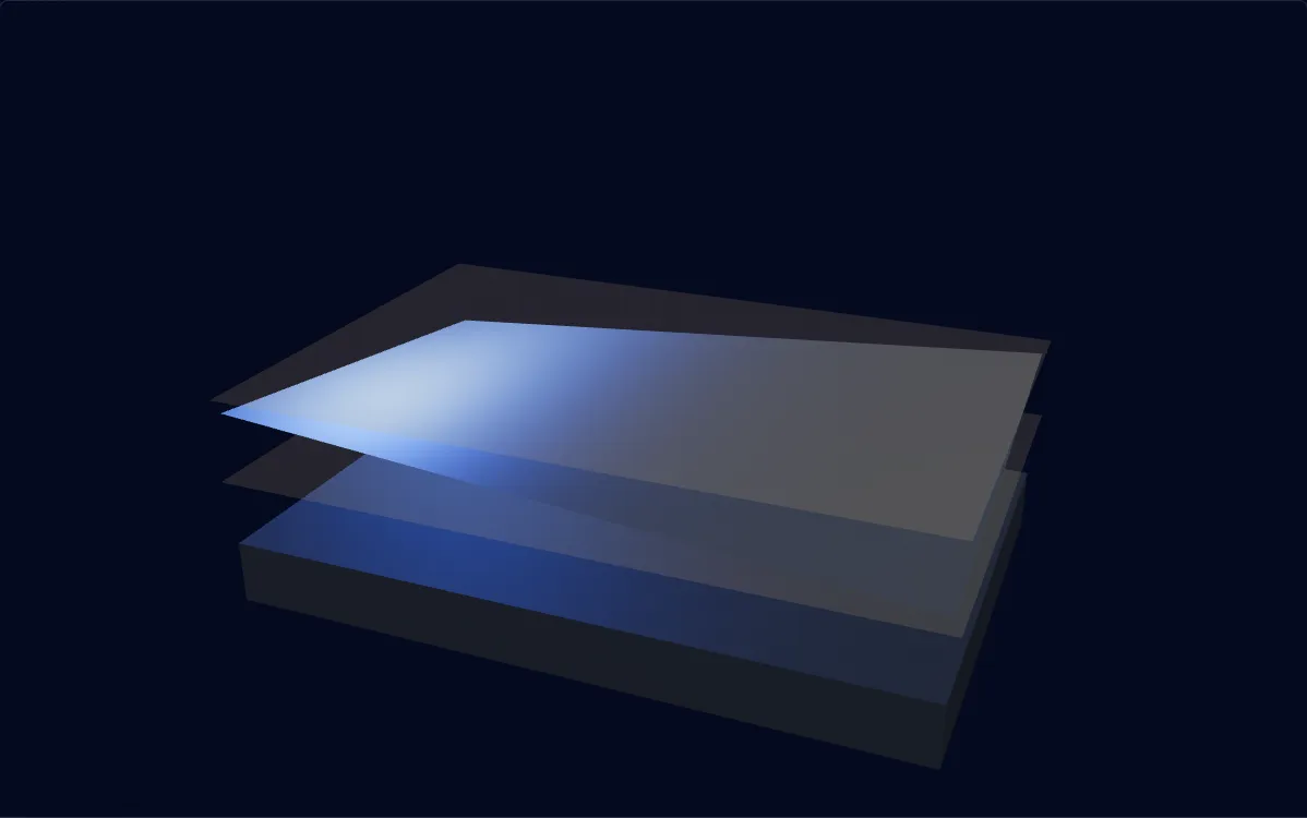
Within tolerance
Drag to exaggerate the deviation. The part is shown far out of scale so the zone stays visible.
Reading the callout
The derived median line of this feature has to lie inside a cylinder 0.1 mm across, coaxial with datum A.
When to reach for it
- A feature where what matters is where the material is centred rather than where its surface lies.
- A feature where the wall thickness around it is what matters, since median points describe that directly.
- Existing drawings that already carry it — which is the usual reason to be reading this page at all.
How it is measured
- Each cross-section is scanned densely enough for its centre to be computed, and those centres define the median line — which is why a CMM or a dedicated form tester is effectively required.
- The datum axis is established from the datum feature first, and every section centre is reported relative to it.
- Enough cross-sections are taken along the length to be confident the worst one has been found, since the requirement applies everywhere.
Getting it right
- Consider circular runout first, since it checks the surface directly, takes a fraction of the time, and expresses what most rotating assemblies actually need.
- Consider position on the feature axis where the concern is location rather than mass distribution, as it is far cheaper to verify.
- Reserve it for the cases where the derived median line genuinely is the requirement, and say so in a note so the supplier knows it was deliberate.
Common questions
Concentricity or runout?
Runout in nearly every case. Runout is read straight off the surface with an indicator while the part turns, so it is quick and needs no computation. Coaxiality is derived from section centres and needs enough measurement to compute them. Runout also catches form error, which most rotating assemblies care about. It earns its place only where the derived median line is genuinely the requirement, which in practice means a wall-thickness concern.
What is the derived median line?
Scan a cross-section, fit a circle to it, and take its centre. Do that section after section along the feature and those centres trace out the derived median line, which is what the tolerance zone contains. It describes where the material is centred rather than where the surface lies, which is why the control is insensitive to a lobed but evenly distributed feature that runout would reject. Older ASME drawings built the same idea from the midpoints of opposed pairs of surface points; ISO builds it from section centres, and that is what to work to on an ISO drawing.
Is concentricity still in the standards?
In ISO 1101, yes — though ISO defines it differently from the ASME version most people met first. ISO uses the symbol for concentricity of a point and coaxiality of a derived median line; the median-points definition many textbooks give is ASME Y14.5-2009, and that is the definition ASME removed in its 2018 revision. The reasoning was that position and runout between them cover every case it was being used for, and that it was frequently applied where one of those was meant. Drawings made to ISO still carry the symbol legitimately; drawings to the current ASME revision do not.
Why is it expensive to inspect?
Because nothing can measure a section centre directly. Each one has to be computed from the measured profile of that section, so a meaningful check needs a dense scan around each cross-section and several sections along the length, then the arithmetic on top. An indicator and a pair of centres cannot do it at all, whereas the same setup reads runout in seconds.
These pages explain the published standards for reference and describe the tolerance zones they define. The values shown in the examples are illustrative. What a given part can hold depends on its geometry, material and process, and is agreed per drawing.