
Circularity
Roundness, judged one slice at a time — which is exactly why a part can pass it and still be tapered.
What it controls
Circularity limits how far a single cross-section may depart from a perfect circle. Each section is judged on its own, independently of every other section along the feature.
Because the sections are independent, circularity controls the shape of a slice and nothing else. A cone, an hourglass and a straight cylinder can all satisfy the same circularity tolerance.
The tolerance zone
Two concentric circles in the same cross-sectional plane, a set radial distance apart. The profile of that section has to lie between them.
Try it in 3D
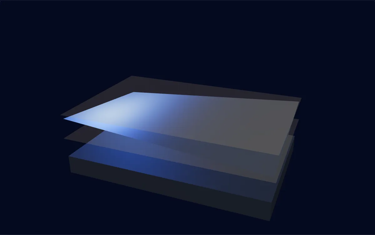
Within tolerance
Drag to exaggerate the deviation. The part is shown far out of scale so the zone stays visible.
Reading the callout
Each cross-section of this feature has to lie between two concentric circles 0.05 mm apart in radius.
When to reach for it
- A bearing journal or a bore that has to run without lobing.
- A sealing diameter where an O-ring has to make contact all the way round.
- A part turned in a chuck or collet, where clamping is the likeliest source of lobing.
How it is measured
- A dedicated roundness tester, which rotates the part against a stylus and separates form from centring error.
- A CMM circle scan, with the software fitting the minimum radial separation of two concentric circles.
- A V-block and indicator for a quick check, remembering that the reading depends on both the V angle and the number of lobes. Some combinations magnify the error two or three times and others cancel it almost completely, so a V-block can return a comfortable reading on a part that is well out of round. Treat it as a screen rather than a measurement.
Getting it right
- Keep circularity for the shape of the slice, and reach for cylindricity when taper and bow matter too.
- Set the circularity value on what the function needs rather than on the diameter tolerance. On an ISO drawing the independency principle of ISO 8015 applies by default, so size and form are separate requirements — and even where the envelope requirement Ⓔ is invoked, it caps roundness error at the size tolerance and no tighter — a lobed section can hold its two-point diameter perfectly while using the whole of that band.
- Measure with a rotary instrument when the tolerance reaches a few micrometres, because a two-point measurement can read an odd-lobed form as very nearly perfectly round.
Common questions
What is the difference between circularity and cylindricity?
Circularity judges each cross-section separately, so it controls roundness alone. Cylindricity judges the whole surface at once, so it controls roundness, straightness of the axis and taper together. Cylindricity is therefore always the tighter requirement for the same numerical value.
Why does a micrometer sometimes miss an out-of-round part?
A micrometer takes a two-point measurement, and a form with an odd number of equally spaced lobes has an essentially constant diameter in every direction — for an ideal three-lobed profile it is exactly constant. A three-lobed part can therefore measure the same across every pair of points and still be visibly out of round. Rotary roundness measurement, or a CMM scan fitted about a computed centre, reads it correctly.
Does circularity need a datum?
No. It is a form tolerance judged within each cross-section, so it references nothing outside the feature. When the requirement is really about the feature running true to another axis, circular runout is the control that says so.
What causes parts to come out lobed?
Most often the workholding. A three-jaw chuck grips at three points and a thin-walled ring will spring back into a three-lobed shape once released. Centreless grinding produces its own characteristic lobing depending on the setup geometry. Where roundness is critical, the practical fixes are softer clamping, a larger contact area, or finishing the part in a different fixture from the one it was roughed in.
These pages explain the published standards for reference and describe the tolerance zones they define. The values shown in the examples are illustrative. What a given part can hold depends on its geometry, material and process, and is agreed per drawing.