
Straightness
The simplest control in the standard, and the one that quietly means two different things depending on what it points at.
What it controls
Straightness controls how much a single straight line element is allowed to bow. Applied to a surface, it is checked one line at a time, in the direction the callout points — a shaft can satisfy straightness along every drawn line and still be barrel-shaped overall.
Applied to a derived axis or median line, with a diameter symbol in front of the tolerance value, it becomes a three-dimensional control: the whole axis of the feature has to stay inside one cylinder.
The tolerance zone
Two parallel straight lines a set distance apart, in the plane of the section being checked — or, when the value carries a diameter symbol, a cylinder of that diameter containing the derived axis.
Try it in 3D
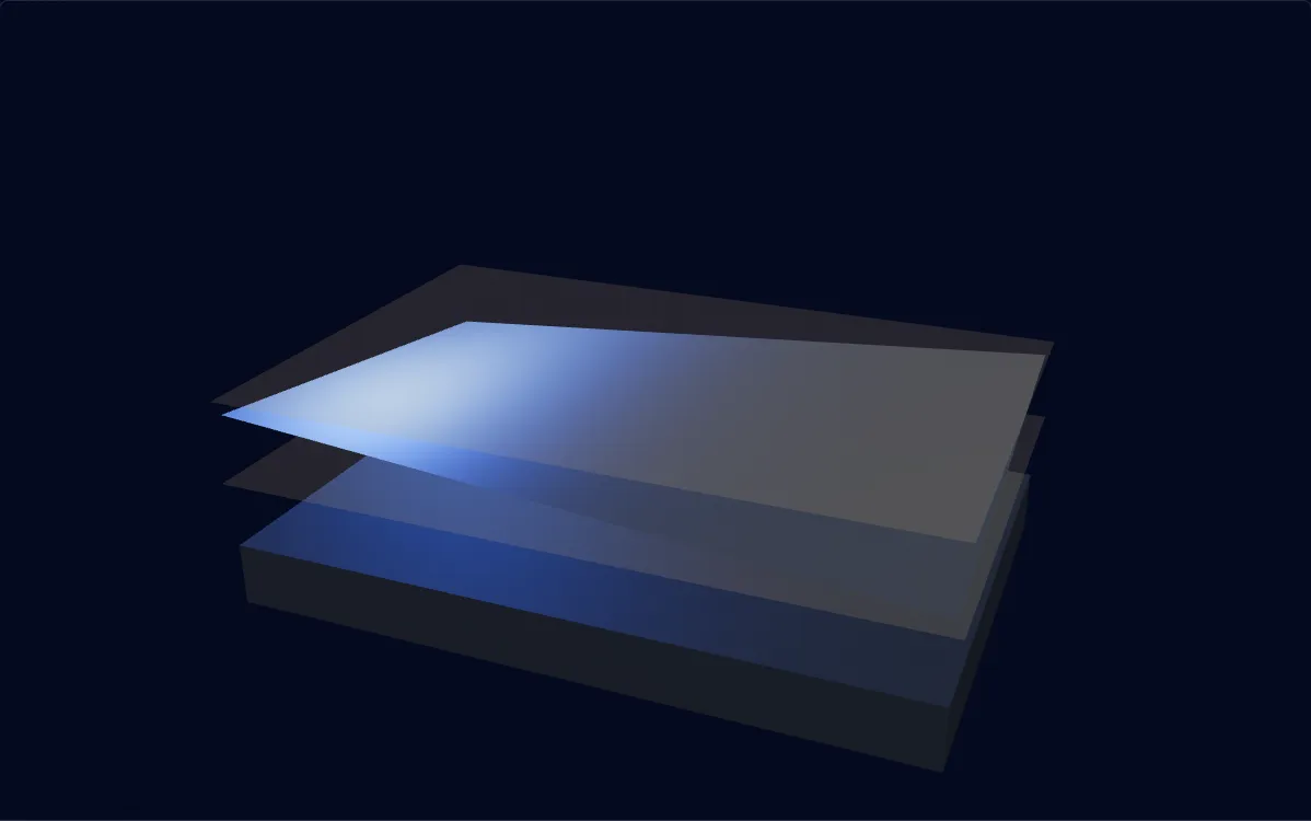
Within tolerance
Drag to exaggerate the deviation. The part is shown far out of scale so the zone stays visible.
Reading the callout
Every line element on this surface, taken in the direction shown, has to lie between two parallel straight lines 0.05 mm apart.
When to reach for it
- A long shaft or rail where bow matters more than overall size.
- A sealing edge that has to sit down evenly along its length.
- The axis of a pin or bore where a controlled amount of bow is acceptable. On an ASME drawing this form of the callout is also how the perfect-form-at-MMC envelope is deliberately relaxed; on an ISO drawing that envelope only applies where Ⓔ was invoked in the first place.
How it is measured
- A dial indicator traversed along the feature resting on a surface plate, remembering that this reads deviation from a line through the contact points rather than the minimum zone, and so is the pessimistic number. Between centres the reference becomes the centres axis rather than a fitted line, so the reading also carries the centres’ own error and any eccentricity of the surface about them — it is no longer straightness alone unless that component is separated out.
- A straightedge with feeler gauges as an indication only, and only well above 0.1 mm — the smallest reliable feeler is around 0.03 mm and the method has no traceability, so it screens parts rather than accepting them.
- A CMM line scan, with the software fitting the minimum zone that contains the measured points.
Getting it right
- Read straightness one line at a time — it says nothing about the surface as a whole, which is what flatness and cylindricity are for.
- Read both the attachment and the symbol: the frame sitting on the size dimension is what shifts the control to the derived median line, and the diameter symbol is what makes that zone a cylinder rather than a slab.
- Make the direction of the line elements explicit rather than relying on where the frame happens to sit. ISO 1101:2017 does this with an intersection plane indicator appended to the tolerance frame, which states the plane the line elements are taken in and removes the ambiguity entirely.
Common questions
What is the difference between straightness and flatness?
Straightness is checked one line at a time; flatness is checked over the whole surface at once. A surface can pass straightness on every line drawn across it and still fail flatness if those lines sit at different heights — the classic case being a twisted surface, whose line elements are straight in the direction they are drawn while the surface as a whole is not flat.
Does straightness need a datum?
No. Straightness is a form tolerance, so it is measured on the feature itself and a datum reference would have no meaning. If the requirement is really about the feature being straight relative to something else, parallelism or perpendicularity is the correct control.
What does the diameter symbol in a straightness callout mean?
The diameter symbol makes the zone a cylinder rather than a pair of parallel lines. What moves the control from the surface to the derived median line is where the frame attaches: on a leader to the surface it controls line elements, placed on the size dimension it controls the derived median line. The two normally appear together, and a callout of ⌀0.05 mm lets that median line wander anywhere inside a cylinder 0.05 mm across, in any direction. ISO 1101:2017 also allows the intent to be stated rather than left to placement: the derived-feature modifier Ⓐ in the tolerance compartment says the median line, not the surface, is what is toleranced.
How tight can straightness realistically be held?
It depends far more on length and material than on the machine. A short ground pin holds single-digit micrometres comfortably; the same tolerance over a metre of thin section is a different problem entirely, because clamping and residual stress move the part more than the cut does. Tolerances at the micrometre level are agreed per drawing against the critical features named on it.
These pages explain the published standards for reference and describe the tolerance zones they define. The values shown in the examples are illustrative. What a given part can hold depends on its geometry, material and process, and is agreed per drawing.