
Circular runout
The quickest geometric check there is: one indicator, one revolution, one number — and it catches two errors at once.
What it controls
Circular runout limits how much a surface rises and falls against an indicator while the part turns about a datum axis. It is judged one cross-section at a time, and every section has to pass on its own.
What it reads is two errors added together: the section may be out of round, and it may be off-centre from the axis it turns about. Runout makes no attempt to separate them, which is exactly why it is quick — and why a part that fails it needs a second measurement to say which of the two is at fault.
The tolerance zone
On a cylindrical surface, two concentric circles a set radial distance apart, centred on the datum axis, in any cross-section perpendicular to it. On a face, two circles that same distance apart measured ALONG the datum axis, on any cylinder coaxial with it — the zone is established one radius at a time, which is why the face case says nothing about what happens between radii.
Try it in 3D
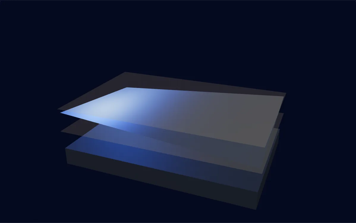
Within tolerance
Drag to exaggerate the deviation. The part is shown far out of scale so the zone stays visible.
Reading the callout
At any cross-section, this surface has to stay within 0.05 mm total indicator movement as the part turns about datum A.
When to reach for it
- A shaft diameter that carries a pulley or a gear, where the part turns in service and eccentricity is what matters.
- A seal journal, where the surface has to run true enough for the lip to follow it.
- A face perpendicular to the axis, where the same symbol controls wobble rather than eccentricity.
How it is measured
- The part is set between centres or in a collet on the datum feature, an indicator is placed against the surface, and the part is turned one full revolution.
- The reading is the full indicator movement at that section — the difference between the highest and lowest points, with no arithmetic.
- Several sections along the length are checked, since each one has to pass separately and the worst may be anywhere.
Getting it right
- Establish the datum axis from the feature the part actually turns on, since runout is entirely a statement about that axis.
- Reach for total runout where taper along the length matters, because circular runout judges each section by itself and a tapered shaft can pass every one.
- Follow a failure with a roundness measurement when the cause matters, as runout gives one number for two different errors.
Common questions
What does circular runout actually measure?
Circularity error and eccentricity from the datum axis, added together. A perfectly round section that is off-centre by 0.02 mm reads 0.04 mm of runout, because the high point and the low point are half a revolution apart. A perfectly centred section that is out of round by 0.04 mm reads the same. The indicator cannot tell the two apart, and neither can the callout.
Circular runout or concentricity?
Runout, in nearly every case. It reads straight off the surface with an indicator while the part turns, which takes seconds and needs no computation, and it catches form error as well as eccentricity. Concentricity is derived from median points and needs a CMM or a form tester to compute them. Concentricity earns its place only when median points genuinely are the requirement, such as a balance concern.
Can runout apply to a flat face?
Yes, and it is a useful callout — but read it carefully. Applied to a face perpendicular to the datum axis, circular runout reads the wobble of that face at one radius as the part turns, together with any waviness around that circle. It does not read flatness: a face that is uniformly coned or dished sits at the same height all the way round each circle and can show zero circular runout while being visibly out of flat. Total runout, which sweeps the whole face, is the control that catches that.
What should the datum be?
The feature the part actually turns on in service — usually the bearing journals. Runout says nothing in the abstract: it is a statement about behaviour relative to one specific axis, so naming the wrong feature gives a number that predicts nothing. Where a part runs on two bearings, the pair are usually named together as a common datum axis.
These pages explain the published standards for reference and describe the tolerance zones they define. The values shown in the examples are illustrative. What a given part can hold depends on its geometry, material and process, and is agreed per drawing.