
Profile of a line
A tolerance zone that follows the shape of the part instead of ignoring it — applied one section at a time.
What it controls
Line profile limits how far a cross-section may depart from the shape the drawing defines. That shape is called true form, and it comes from theoretically exact dimensions, so the zone follows the curve rather than sitting square to anything.
It is judged one section at a time, which is what separates it from profile of a surface. A part can satisfy line profile at every drawn section and still drift between them.
The tolerance zone
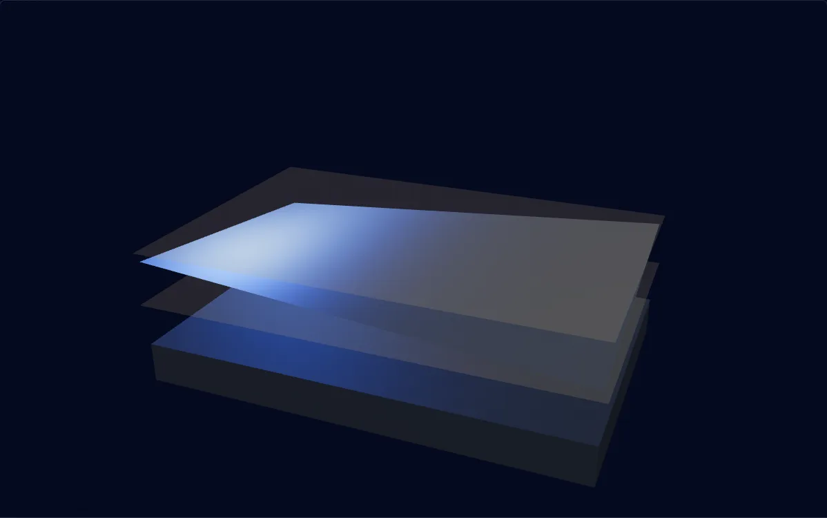
The space between two lines enveloping circles of the stated diameter whose centres run along true form — in practice a pair of curves offset either side of true form, the stated distance apart in total, in each cross-section. The envelope construction only differs from a plain offset at sharp concave corners.
Try it in 3D
Within tolerance
Drag to exaggerate the deviation. The part is shown far out of scale so the zone stays visible.
Reading the callout
Each cross-section of this surface has to lie between two curves 0.05 mm apart, following true form, centred on it.
When to reach for it
- An extruded or drawn section, where every cut through it has the same shape and that shape is what matters.
- A cam or a guide track, where a follower rides one section at a time.
- An aerofoil or blade section given as a table of points, which line profile can control directly.
How it is measured
- A CMM scans the section and the software fits the measured points against the nominal curve, reporting the deviation either side of it.
- An optical comparator or profile projector overlays the section on a drawn chart at magnification, which is quick where the tolerance allows it.
- A form gauge cut to the nominal shape gives a fast production check once a first article has been verified properly.
Getting it right
- Reach for profile of a surface where the shape has to hold between the drawn sections as well, since line profile judges each one alone.
- Name datums when the profile also has to sit in a particular place, because without them the zone floats and controls form only.
- Define true form with theoretically exact dimensions or a supplied model, since the zone has nothing to follow until the nominal shape is unambiguous.
Common questions
Line profile or surface profile?
Line profile is judged in each cross-section independently, so it is the right control for a shape that is constant along its length and is used one section at a time — an extrusion, a cam track. Surface profile judges the whole surface at once and is the right control for anything that curves in two directions or has to hold its shape between sections. Surface profile is always the stricter requirement at the same value.
Does profile need datums?
Only if the requirement includes where the surface sits. Without datums the zone floats and follows the surface, so profile controls form alone — the shape has to be right, but it may be anywhere. Add datums and the zone becomes fixed in space, so the same callout then controls form, orientation and location together. That flexibility is the reason profile is the most versatile symbol in the standard.
Is the zone centred on the true profile?
By default yes: half the tolerance either side. The standard also allows an unequally disposed zone, where more of the tolerance sits on one side than the other, which is useful when a surface may be allowed to grow but not shrink. ISO writes it as UZ followed by the signed offset of the zone centre from true form; ASME writes Ⓤ followed by the amount lying in the direction of added material. The two differ in what the number means, so stating the intent in a note alongside either saves a good deal of correspondence.
What is true form?
The exact shape the drawing intends, defined by theoretically exact dimensions, a table of coordinates, or the CAD model itself. It carries no tolerance of its own — all the permitted variation lives in the profile zone. That is why a drawing using profile has to define the nominal shape unambiguously, and why supplying the model alongside the drawing is usually the practical answer.
These pages explain the published standards for reference and describe the tolerance zones they define. The values shown in the examples are illustrative. What a given part can hold depends on its geometry, material and process, and is agreed per drawing.