
Angularity
The general case of the orientation family — and the one that needs a boxed angle before it means anything at all.
What it controls
Angularity limits how far a surface or a derived axis may depart from a stated angle to a datum. Unlike parallelism and perpendicularity the angle is written out, as a theoretically exact dimension in a box — a TED in ISO, a basic dimension in ASME.
The angle being theoretically exact is what makes the control work. Such a dimension carries no tolerance of its own, so all the permitted variation lives in the tolerance zone and nowhere else.
The tolerance zone
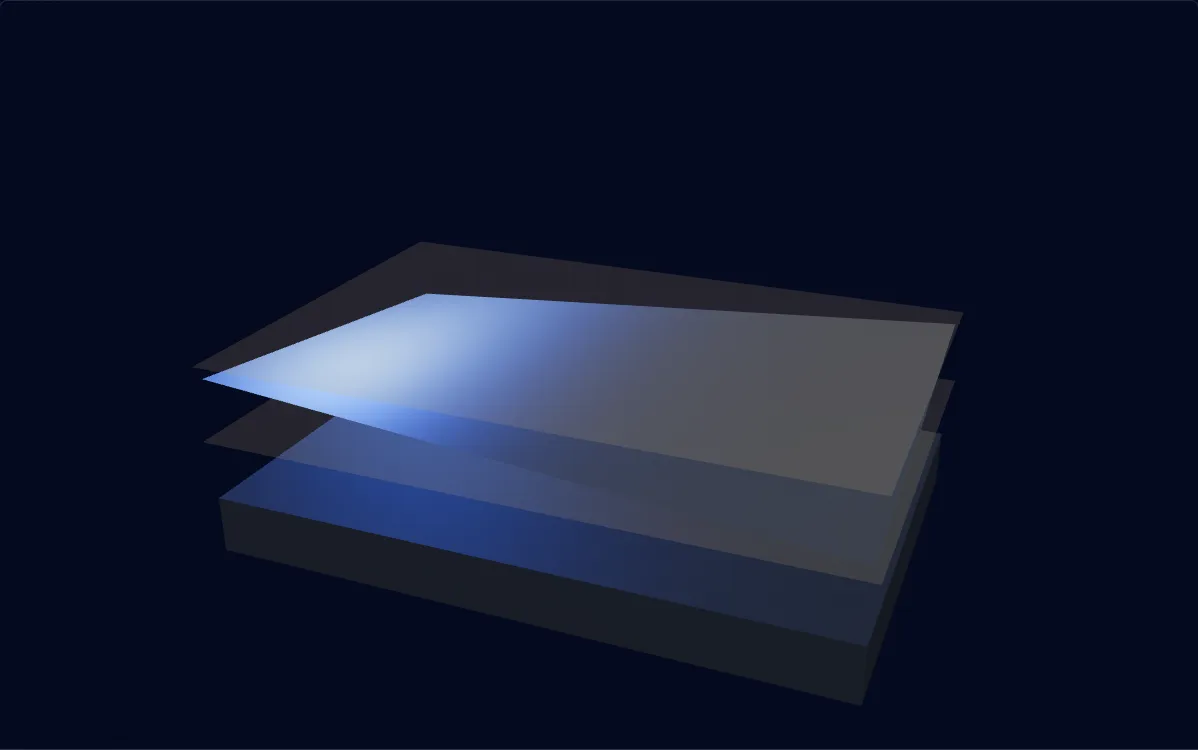
Two parallel planes a set distance apart, held at the stated theoretically exact angle to the datum — or, when the value carries a diameter symbol and the frame sits on the size dimension, a cylinder of that diameter held at that angle, containing the derived axis.
Try it in 3D
Within tolerance
Drag to exaggerate the deviation. The part is shown far out of scale so the zone stays visible.
Reading the callout
This surface has to lie between two planes 0.05 mm apart, set at the boxed theoretically exact angle to datum A.
When to reach for it
- A chamfered or ramped face that a mating part slides along at a set angle.
- A dovetail or a wedge, where the angle carries the load and the fit depends on it.
- An angled hole, where the axis has to hold its direction relative to a face.
How it is measured
- A sine plate or sine bar tilts the part by the theoretically exact angle so the toleranced surface becomes horizontal, after which it is an ordinary indicator sweep.
- A CMM measures the surface directly in the datum frame and fits the zone at the stated angle, with no tilting needed.
- An angle gauge block set gives a quick comparison for angles that happen to fall on standard combinations.
Getting it right
- Write the angle as a theoretically exact dimension in a box, since a toleranced angle alongside an angularity callout gives two competing statements of the same requirement.
- Consider profile of a surface for a face angled in two directions at once, since one profile callout replaces a pair of angularity callouts. It is easier to specify and easier to reconcile — not easier to inspect, since profile to datums needs a CMM with the model loaded while angularity on a simple flat face is a surface plate job.
- Name the datum the angle is measured from, because an angle relative to nothing in particular has no meaning on a part with more than two faces.
Common questions
Why does the angle have to be basic?
A theoretically exact dimension carries no tolerance of its own, so every bit of permitted variation is described by the tolerance zone. If the angle carried its own plus and minus as well, the drawing would be stating the same requirement twice in two different ways, and the two would rarely agree.
Angularity or profile of a surface?
Angularity fixes the orientation of a flat face at one angle to a datum. Profile of a surface controls the shape and can control orientation and location at the same time, and it handles faces angled in two directions or curved faces that angularity cannot describe. For a simple flat ramp, angularity is clearer; for anything compound, profile is the better tool.
How does a sine plate help?
It converts the problem into one an indicator can read directly. The plate is tilted by exactly the theoretically exact angle using gauge blocks, which brings the toleranced surface parallel to the surface plate, and from there the check is an ordinary sweep for total indicator movement. It is a neat trick and still the fastest shop-floor method where no CMM is available.
Does angularity control form as well?
Yes, for a surface callout. The zone is bounded by two parallel planes, so a surface that fits inside it is within a flatness zone of the same width at the same time. As with parallelism, that makes a separate flatness callout at the same value redundant.
These pages explain the published standards for reference and describe the tolerance zones they define. The values shown in the examples are illustrative. What a given part can hold depends on its geometry, material and process, and is agreed per drawing.