
Perpendicularity
Squareness has a formal definition, and this is it — with two quite different meanings depending on what the frame attaches to.
What it controls
Perpendicularity limits how far a surface or a derived axis may depart from exactly 90 degrees to a datum. Like parallelism the angle is implied, so only the tolerance value appears in the frame.
What the callout attaches to changes it completely. Pointed at a surface it gives a zone between two planes; placed against a size dimension, with a diameter symbol, it gives a cylindrical zone the feature axis has to stay inside.
The tolerance zone
Two parallel planes a set distance apart, held square to the datum — or, when the value carries a diameter symbol and the frame sits on the size dimension, a cylinder of that diameter square to the datum, containing the derived axis.
Try it in 3D
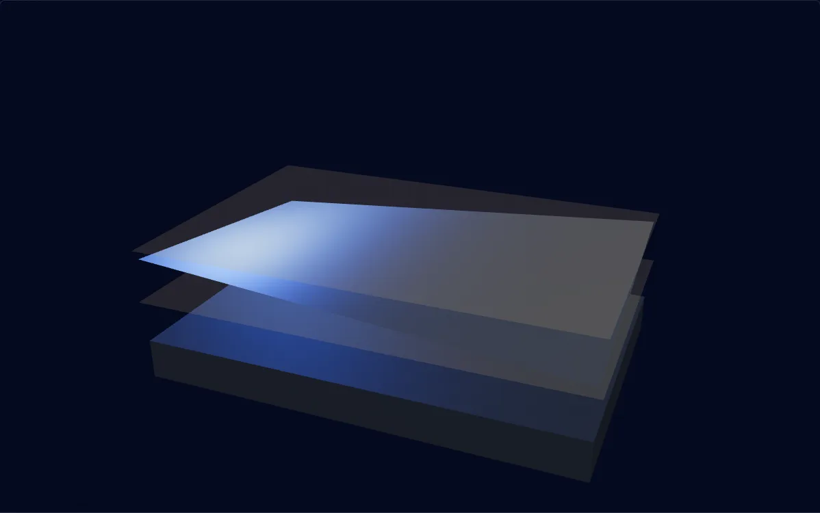
Within tolerance
Drag to exaggerate the deviation. The part is shown far out of scale so the zone stays visible.
Reading the callout
This surface has to lie between two planes 0.05 mm apart that are square to datum A.
When to reach for it
- A hole that has to take a dowel or a bolt standing square to a mounting face.
- A shoulder that locates a bearing, where a face out of square loads the bearing unevenly.
- A face that will be used as a secondary datum, which has to be square to the primary before anything is measured in that frame.
How it is measured
- The datum face is set down on a surface plate and the toleranced face is checked against a square, or with an indicator on a height gauge.
- For an axis, a gauge pin is fitted in the bore and the indicator reads the pin, which magnifies the error usefully over the pin length.
- A CMM establishes the datum plane from the datum feature and then fits the toleranced surface or axis in that coordinate system.
Getting it right
- Check whether the frame points at the surface or at the size dimension, because a surface zone and a cylindrical axis zone are different requirements wearing the same symbol.
- Keep the tolerance proportionate to the length it acts over, since a hole 10 mm deep and one 100 mm deep are different jobs at the same value.
- Name the datum that the part actually seats on in service, so the measured result predicts the assembly.
Common questions
What changes when the callout applies to an axis?
The zone changes shape. Applied to a surface, perpendicularity gives a zone between two parallel planes and the surface has to fit inside it. Applied to a derived axis with a diameter symbol, the zone is a cylinder standing square to the datum, and the axis has to stay inside that cylinder in any direction. The second is usually what a hole needs.
Is perpendicularity just angularity at 90 degrees?
Effectively yes, and the standard treats them as members of the same family. Perpendicularity exists as its own symbol because 90 degrees is by far the most common case, and having a dedicated symbol saves writing a theoretically exact angle on nearly every drawing.
Does perpendicularity control flatness too?
For a surface callout, yes — the zone is bounded by two parallel planes, so a surface inside it is also within a flatness zone of the same value. For an axis callout the question does not arise in the same way, though the straightness of that axis is limited by the cylindrical zone it has to stay inside.
What makes perpendicularity difficult to hold?
Depth, mostly. The error is an angle, so it grows with the length it acts over: a tenth of a degree is a few micrometres across a short face and a visible gap across a long one. Deep holes are the usual difficulty, because a drill wanders and the error accumulates the whole way down. Where it matters, the practical answer is spotting and boring rather than drilling alone.
These pages explain the published standards for reference and describe the tolerance zones they define. The values shown in the examples are illustrative. What a given part can hold depends on its geometry, material and process, and is agreed per drawing.